This project has a video!
This project is on GitHub!

During the summer of the Covid-19 lockdown, I had two small problems with a common solution:
- I was bored out of my mind
- I needed my glasses to see the time at night
And so, the solution was of course to spend the summer about electronics and to build something from scratch to solve my time problem. Or at least I thought it was obvious. Maybe I was just looking for excuses. For whatever reason, all of my recent projects seem to relate to either keeping time or LEDs. It probably helped that one of my favorite YouTube channels, Mitxela had somewhat recently done a video on an extremely accurate GPS-based clock.
Either way, I knew what had to be created: a clock big enough for me to read with or without glasses and custom enough that I would have a ton to complete it. By the end of the project, I had touched on just about every skill I thought possible, from 3D printing to web APIs.
Design Criteria
For me to consider this project a success, I needed to create a device that would at the very least:
- Set and keep reasonably accurate time
- Be readable to me without glasses
- Be dimmable enough to not floodlight the room at night
And assuming the very basics were possible, I wanted:
- USB powered
- Support for multiple time zones
- Interior/exterior temperature data
Design Decisions
To begin the design process, I had to pick a way to display the time. I quickly found several options that would fit the criteria:
- An RGB matrix
- A binary clock
- A segmented display
As much as I love the look of an RGB matrix and all the designs I could make, even small scale matrix displays were well out of my price range, and DIY-ing one would be far out of my skill set. I also couldn’t find information about the typical minimum brightness, and there was no way I could power that many LEDs from a USB port. As such, I moved on to evaluating my other choices.
The binary clock would be a small 6*4 matrix of LEDs on a board, and the grid layout would mean that I could probably read it from far away. This would be fairly simple to build, and would probably print as one big piece. Unfortunately, reading binary clocks isn’t a skill they teach in elementary school, and I didn’t have faith in myself co1nverting from base two while half asleep and just wanting to roll back over.
The final option of the three, a segmented display, seemed like the winner. Out of the three options, a segmented display only requires one light source to illuminate a large digit, and can be scaled easily. It would require a fair number of LEDs, but nothing unmanageable. It would also be instantly readable, as segmented number displays are all around us. As long as the digits were large enough and the LEDs able to dim enough, the project should be a success.
That decision made everything else fall into place.
- To space the LEDs far enough apart, I needed my own mounting solution: a PCB.
- To make the blinding raw LEDs readable, I needed some way to diffuse them.
- And finally, to make the features work I needed a controller able to connect to the internet, but low enough power and small enough to not influence the footprint, something Arduino compatible.
And so, I made my decisions. I would be designing a seven-segment based display using custom PCBs, an Arduino-compatible microcontroller, and 3D-printed parts. Looking back with more knowledge, these are all solutions that anyone would take as given, but I had to do a lot of research before coming to these conclusions.
Design Process
Just as I had dreaded hoped, I had very little experience with much of what was required. Most of my experience before this point had been tinkering with a Raspberry Pi and small pre-made add-ons or breadboards, or classes in school that repeated the same basic high level programming tutorials. I had no idea at all how to approach custom PCBs, low-level programming, and especially no idea how to control the large number of LEDs. Thankfully, just about every problem I ran into has already been solved a hundred different ways, and I was able to lean on blogs and YouTube videos to find the best ones. In the end, I just had to pick solutions to learn about and eventually glue them together. (That’s engineering!)
3D-Printed Parts
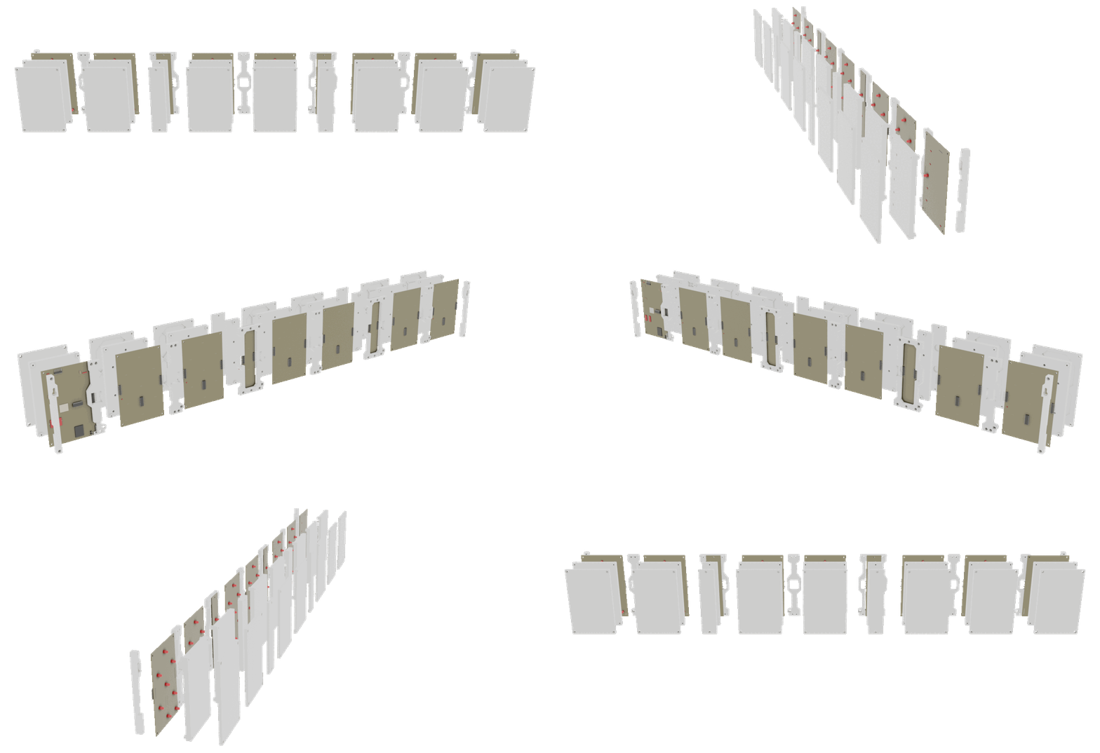
I began with what I was most familiar with, designing the 3D-printed parts in Fusion 360. I figured that if I could get the look and outer shape of the diffuser right, I could design PCBs to fit into the parts, and then program the device after having all the hardware done. This approach, although not quite how I would do it again, ended up working well and allowed me to iterate bit by bit.
I designed the diffusion layer and PCB attachments parametrically. This proved extremely useful, as during the design process I tweaked just about every dimension multiple times to get the final fit right. This process was very lengthy. Just getting the shape wasn’t that hard, but to incorporate all the mounting points, designing connections between each digit, and making slots for each component, all while keeping the file easily editable was a challenge.
After I had the look I wanted in CAD, I began to tweak it in the real world. To test the diffusion, I would print a test section (just a single digit of one display) and attach an LED to the back. Because the test part was so small, I printed several pieces with different parameters (chamber depth, front plastic depth, etc.) at a time and experimented with them all until I found a combination I liked. The parametric design made this super easy, and I’m glad I was taught to design that way.
Eventually, after going through a similar process for other parts such as the mounting brackets and PCB attachments, I moved on to the hard part.
PCB Design
Before this project, I had never created a PCB, used EDA software, or done any kind of power circuitry (even on a breadboard). I was going in blind. After doing quite a bit of research, I installed Autodesk Eagle (mostly because it integrated with Fusion 360). Upon opening it, I was met with buttons on top of buttons with icons that might as well have been hieroglyphics. Out of all the things I learned during this project, the majority of them came from designing the PCBs.
After researching how to use the software and completing a couple of tutorial boards, I concluded that I would need to split my learning into several sections:
- Power
- To handle and possibly filter the 5V coming from the USB port, and to change the voltage to whatever other components would need
- Controller
- Some sort of microcontroller I could program to keep the time and keep the display fed
- Some way to connect the microcontroller to the LEDs
- Some additional sensors
- Display
- The actual layout of the LEDs on a board designed to fit in the enclosure
- Connections and Routing
- The routing for power and data between every component on every board
- Some way to make each digit connect, while ideally being as simple as possible
With those goals in mind, I began tackling the sections one at a time.
Power
In addition to all the other firsts, this was my first project with dedicated power management. Previously, I had only worked with the power from a Raspberry Pi’s GPIO. But for this project, which needed at least 49 LEDs and didn’t even use a Raspberry Pi, I needed something more custom.
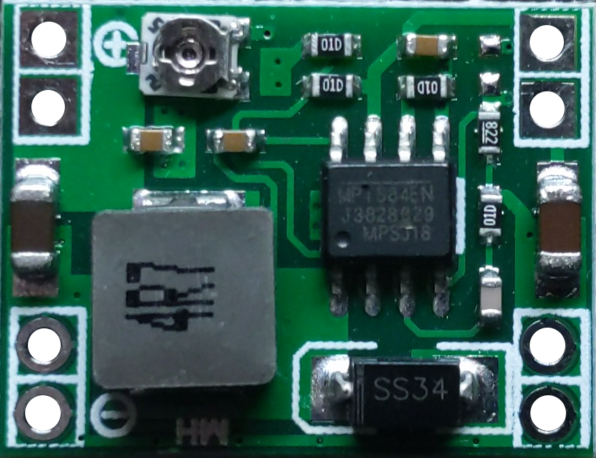
So, I listed the power requirements (power and voltage) of each component, totaled them up, and began searching. I wanted the input to be USB, so the power input should be designed for 5V, but the LEDs and microcontrollers I was looking at used 3.3v. This being my first project, I refused to “design” my own voltage converter. After doing some research I found that a dc-dc buck-boost board would probably be a good fit for what I needed. After doing some more napkin math, I went on Amazon and found a small board with seemingly the right specs. I created my own PCB footprint for the device after some measuring, and incorporated it into my design.
Controller
Before this project, I had never used an Arduino or anything that was programmed at such a low level. As such, I spent a lot of time learning about the ecosystem before I decided on a microcontroller to use.
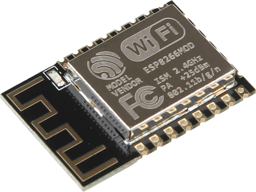
In the end, I decided to use an ESP-12. It is essentially the middle child between the ubiquitous but gpio-sparse ESP8266 and the extravagant but overkill ESP32. It had easy WiFi connectivity, support with most existing Arduino libraries, and it had enough pins to comfortably connect to all of the parts I wanted. Although this specific line of microcontrollers isn’t most people’s first taste of the Arduino ecosystem, it was mine.
Display
Laying out the LEDs was the easy part. I drew out the design on graph paper, picked coordinates for the LEDs to be at, and converted the grid to real world units in Eagle. The location of the LEDs on the display was a design constraint, so the majority of the time spent on this step was just fighting the software. A parametric “grid system” ended up being a useful design tool, which I also used to line up the connectors.
Schematic Design and Routing
Putting all the electronics together was by far the hardest, as it was my weakest area. These components were completely new to me, and I knew that a single sufficiently incorrect misstep could fry all of my parts or make me re-order boards.
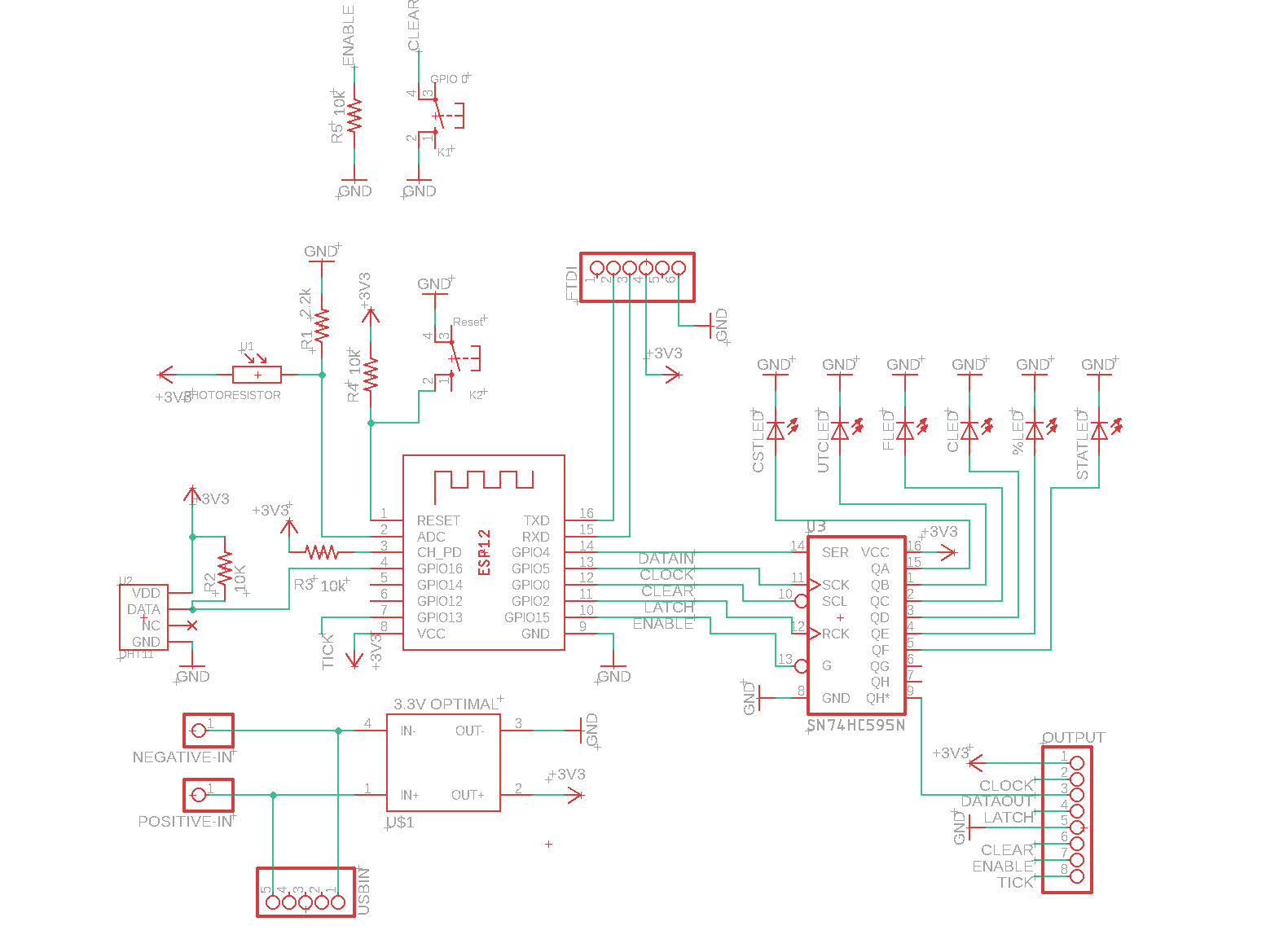
So I took it slow. The full schematic was up first. I made heavy use of Adafruit and Sparkfun’s public designs to see what components others usually include together. From those, I was able to conclude how to wire up the sensors, how to route power, and what connections the ESP-12 needed to work correctly. This process was very slow, as I cross-referenced my design with data sheets and repeatedly double-checked everything (all while struggling against eagle).
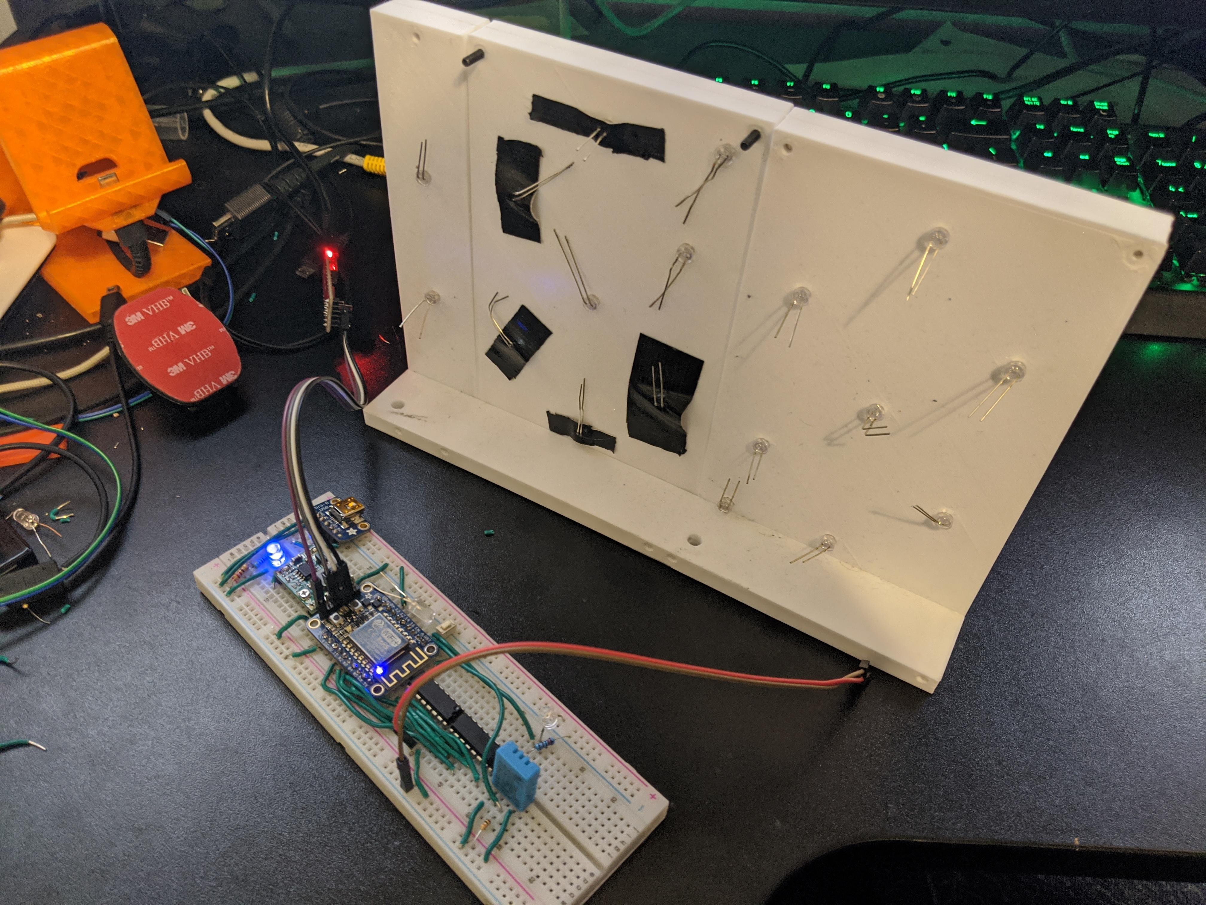
As I was creating the digital design, I was actively testing what I could on a breadboard. This highlighted some important errors, which was good! Luckily nothing exploded during this process (besides a shift register). Through my breadboard debugging I was able to figure out that I was missing some resistors, that I had planned to use incompatible pins in my design, and that I would have messed up the programming port pinout completely!
I’m glad I tested my design on the breadboard, as it highlighted flaws that would have been a pain to fix later.
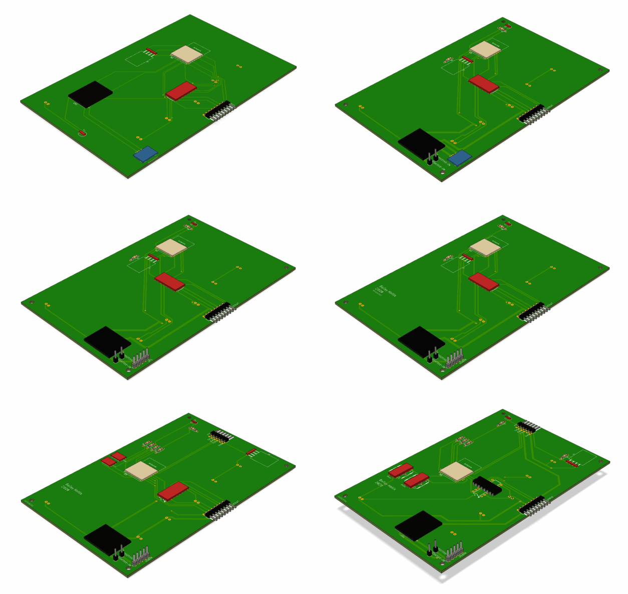
So, I moved on to creating the physical board layout. I started by creating PCB footprints for the custom components I couldn’t find in Eagle libraries, mainly the DC-DC regulator and some parts of the ESP-12 footprint. Getting everything to play nicely between the different parts of Eagle and syncing the components into Fusion 360 was excruciatingly painful, and is a process I hope to avoid in the future. Next, I placed the components on the board generally where I thought would make sense and checked their location against the plastic models I created earlier.
Finally came routing. I was able to use the auto-router for the display boards and tick boards, but I insisted on doing the controller board myself. This process took a long time, but was kind of fun. I got to watch everything come together, and I learned how to set up the appropriate board design rules.
After quadruple-checking everything one more time, I pulled the trigger and ordered the PCBs and components.
Assembly
And then the boards and parts arrived! I was impressed with the quality of the JLCPCB boards, although I doubt they were impressed with the quality of my work. 😉
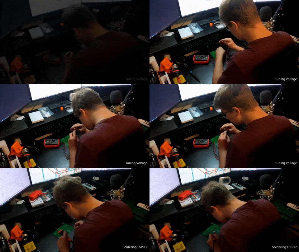
Assembly was perhaps the simplest part, as I already knew the design by heart at this point and had plenty references I needed. If all went smoothly, I could test my design by soldering everything together and uploading a quick test.
Unfortunately, not everything did go smoothly. After soldering together the controller board, I was unable to program it. After much troubleshooting, I discovered that I had swapped around the TX/RX labels the programming port (rookie mistake). Once programming was possible, I was able to flash the ESP-12, read back data from the sensors, and flash an LED on the display pin. This meant that just about everything on the controller was working, and I had designed my own (simple) microcontroller board!
Next was soldering together the display and tick boards, which also came with some issues. Somehow, during all of my checking, I failed to notice that I mismatched GND symbols between different files, meaning that the GND pins of the LEDs had been connected to each other, but not between boards. This required a bodge wire on each display to fix, but after writing a small test script, the digits were also working. All the PCBs were working, without any major issues!
To round out the assembly came the lengthy process of printing all the plastic pieces and screwing the assembly together. Each PCB screws into a plastic panel, and each panel/PCB combo gets attached at the back.
And so, I had a device in front of me that I had designed from nothing! But now, I had to give it brains.
Programming
As a reminder, the code for this project, along with the rest of the design files, can be found in this GitHub.
The programming, although one of the most important parts, was markedly unremarkable for this project. For the most part, my inexperience led me into a hacked together solution where I glued together libraries for the features I wanted and spliced in my own code to drive the displays.
The operation of the clock alternates between 5 different “modes”:
- Local time (CST for me)
- Universal time (UTC)
- Temperatures (in Fahrenheit)
- Temperatures (in Celsius)
- Percent Humidity (%)
First, the ESP-12 establishes a WiFi connection, then it initializes all the appropriate libraries and begins to display information.
To drive the displays, I used an array to map the character corresponding to each number to an 8-bit binary value which represents the LEDs. Using the data from the sensors and internet, I compile the displays together.
To operate the first two modes, the ESP-12 connects to a Network Time Protocol server when the clock turns on, then keeps the current time in memory. Unfortunately, the ESP-12 is much worse at keeping accurate time than I had hoped for, so it needs to re-sync with the server roughly every 5 minutes. This time data keeps track of the local time and UTC time, for their respective modes.
To operate the third, fourth, and fifth modes (weather information), the ESP-12 reads data from the OpenWeatherMap API and combines it with data from the onboard DHT-11 temperature/humidity sensor. The 6 digit display is just enough to display two three-digit values, perfect for this application. The interior/measured value goes to the right three digits, and the exterior/API value is shown on the left three digits.
Finally, I apply the rest of the processing to change the display brightness, switch the active mode, keep up the API connections, and do some basic calibration. Most of the code runs in one large refresh loop. It certainely isn’t the most elegant solution, but for a first attempt in c++ and in Arduino, I was just happy that it worked.
Conclusions
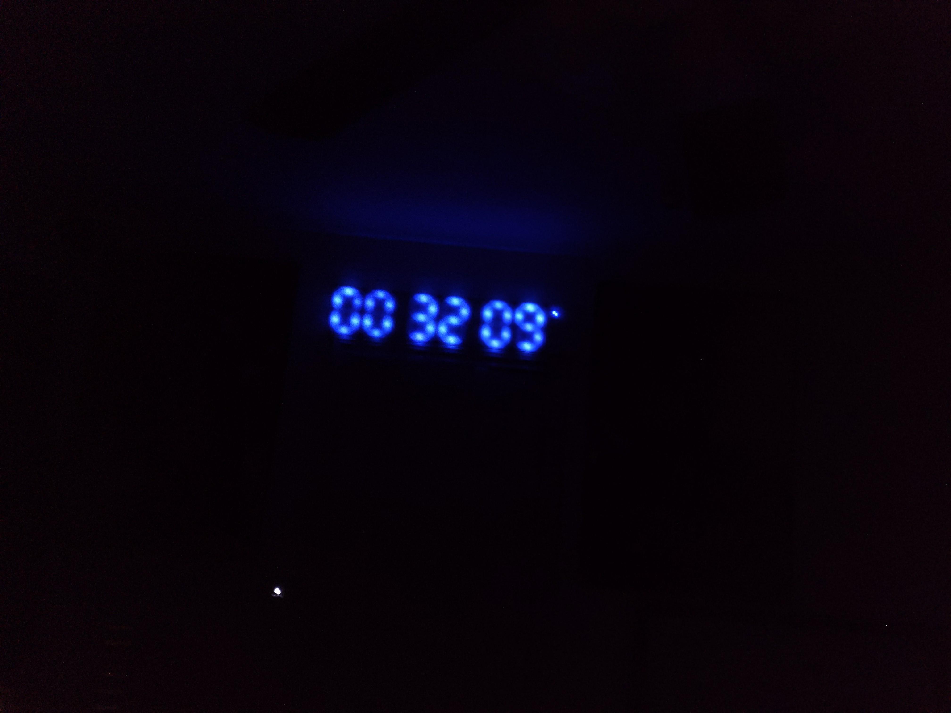
Now that the project is done, I am quite happy with how it turned out. I think it looks very cool, and the final product managed to accomplish the design goals I laid out at the start. I can easily read it without my glasses and I learned an astronomical amount in the process of completing this project.
If you want to see the device in action, I would suggest taking a look at the end of the video, where I show it cycle through all the modes.
Future Improvements
All things considered, this was a great first attempt. That doesn’t mean it was perfect, however. If I were to do this project again, I would address these (somewhat glaring) areas:
- Driving LEDs directly from shift registers is very bad:
- I should have used transistors or some other switch to power the LEDs
- Alternatively, I could adopt another style of LED, such as Neopixels which chain together
- Relying on repeated NTP pings is not a good practice:
- I should have included an RTC as a separate chip, and offload the timekeeping to it.
- Alternatively, I could have used an external oscillator or better microcontroller, with more time-sensitive code.
- The final code was barely readable, and not very configurable:
- To fix this, I would need to take more time to improve the programming. I would focus on reusability, and likely implement more of the object oriented structures and patterns I have learned since this project.
